
TEST & CALIBRATION — HC-Bench
Turn your test bench into an automated pump tester
Custom electronics, sensors and control software that take control of a manual diesel injection-pump test bench and run the measurement sequence unattended — identifying the control unit, driving the bench, judging every point against the factory tolerance, and documenting the result.
A retrofit for the bench you already own. Your machine, its drive motor, tank and plumbing stay where they are.
What it is
HC-Bench is a retrofit, not a new bench. Your bench, its drive motor, tank and plumbing stay; we supply the control electronics, the sensor set and the software, and convert the machine.
Then it takes over. The operator mounts the pump, connects it, and starts the run. From there the system identifies the pump’s control unit over its diagnostic line, looks up that exact Bosch part number in its database, unlocks the immobilizer if the pump is a locked Ford unit, powers the bench, drives the motor to each test speed under closed-loop control, commands the pump’s own electronics through the test points, waits, measures, judges each point against the Bosch tolerance, calibrates the pump’s idle timing if asked, clears the fault memory, and shuts down safely — stopping the bench by itself on a critical alarm, a loss of flow, or a lost connection.
The conversion is performed by Herlic Components, or by a technician we have trained.
What it automates
- Pump identification. Reads the control unit over K-Line and recovers the Bosch part number, model reference, data record, both software versions, the serial number, the stored idle-timing value and the fault codes. The part number selects the test plan automatically, and an unrecognised pump stops the run rather than guessing.
- Immobilizer unlock. Locked Ford control units are unlocked and virginized as part of the sequence, then verified, so the pump can go to a different vehicle. Skipped automatically on pumps that do not need it.
- Bench control. Powers the pump, ramps the motor to each test speed and holds it under closed-loop control against measured shaft speed, sets rotation direction, and runs the oil pump.
- Test execution. For each phase: reach speed, settle, command the pump’s fuel quantity, injection angle and pre-injection quantity, condition for the specified time, then sample every measured channel at the specified rate for the specified duration. Pump commands are zeroed between phases.
- Evaluation. Each measured point is compared against the Bosch nominal and tolerance. Pass or fail is decided per point, per phase, per test and overall.
- Idle calibration. Optional and fully automatic. The system measures, solves for a new trim value, writes it to the control unit, power-cycles the pump by itself where required, re-conditions and re-measures — up to eight iterations — then commits the best value to the control unit’s permanent memory.
- Fault-code erase. Clears the control unit’s fault memory as a final step, so the pump leaves with a clean record and the report shows it.
- Safety and shutdown. The run is abandoned automatically on a critical bench alarm, on zero return flow while the bench is turning above 300 rpm with the oil pump on, on a control-unit status reaction, on a speed or temperature target not reached in time, or on loss of either the CAN or the K-Line connection. Teardown always stops the drive, drops the direction relays, zeroes the pump commands and spins the oil pump down.
- Record keeping. Every completed run is written to disk immediately, with every individual measurement sample.
What still needs a human
Unattended means the run, not the job. Once the pump is mounted and Start is pressed, identification, unlock, speed control, command injection, conditioning, sampling, judgement, idle calibration, fault-code erase and shutdown all proceed on their own. What the operator still does:
- Mounting and connecting the pump — plumbing, harness, and selecting the correct injector, tube and valve set. Nothing detects or verifies what tooling is fitted; it is operator-attested.
- Selecting the supply voltage. 27 V or 13.5 V is a manual switch on the power supply. The software knows which the pump needs and puts a message on screen telling the operator to change it — it cannot switch it, and cannot read back what was actually set.
- Bringing the oil to temperature. The heater and both coolers are manual controls, so conditioning the oil is the operator’s job and their judgement.
- The leak check. Before the oil pump starts, the operator confirms oil level and connections on screen. It blocks the run by default.
- Starting the run, and logging in where a test or the report requires it.
- Generating the report. Nothing exports automatically.
There is no robotic handling and no automatic tool change.
What it measures
The bench and the pump’s own electronics are read at the same time, so a measured result and what the control unit made of it sit side by side.
From the bench
- Delivery quantity — the pump’s fuel delivery, the primary measured result and what most test points are judged on. Normalised to a 1000 rpm reference.
- Return and overflow quantity — also the zero-flow safety interlock.
- Injection advance angle — measured from the control unit’s own timing signal, or from the injector pulse on pumps that do not provide one. Selected automatically.
- Shaft position for lock-angle capture.
- Pressure — two channels, including transfer pressure.
- Temperature — four channels: tank, inlet, outlet and a fourth.
- Bench speed, which is also the feedback for the speed loop.
- Bench alarms — decoded to named conditions, each with its own criticality.
From the pump’s electronics
- Reported speed, fuel temperature, solenoid energising time and injection-angle feedback
- Commanded fuel quantity, control-unit status and self-test words
- Immobilizer state and stored fault codes
- Software versions, serial number and the stored idle-timing calibration value
Not measured: solenoid drive current and supply voltage. “HC-VCI” measures both, if you need that on the bench as well.
Pumps and control units
- Bosch VP30 and VP44 distributor injection pumps.
- 110 pump part numbers in the shipped database, reachable through 147 identifiers once the alternative diagnostic identifiers are counted. The same database HC-VCI uses.
- 109 original Bosch factory test plans — each giving speed, commanded quantity, commanded angle and a delivery target with its tolerance band.
- PSG5 control units — PSG2/PSG5 Opel, PSG5 with pre-injection, and PSG5 with pre-injection for Ford including the immobilizer unlock. Three diagnostic protocol variants are handled, so older and newer control units both read. Not PSG16.
The test sequences
The tests ship with the system, derived from the Bosch factory test specifications for each part number — test speeds, commanded values, nominal delivery and tolerance band per test point.
The operator cannot author or edit a test, a phase, a target value or a tolerance. That is deliberate: the workshop tests to the factory specification, and nobody can quietly widen a tolerance to make a pump pass.
What the operator can change, per run:
- Enable or disable individual phases before a run
- Re-run only the phases that failed
- Turn automatic idle calibration on or off
- Measure advance from the injector pulse instead of the control-unit signal
- Three global tolerance slacks in settings — pressure, advance angle and delivery quantity
Pass or fail is decided on the mean of the samples for each measured point against the nominal ± tolerance, with an additional proportional allowance on delivery and transfer-pressure tests. A phase passes only if every point passes; a test passes only if every phase passes; phases marked critical stop the test immediately on failure.
The report
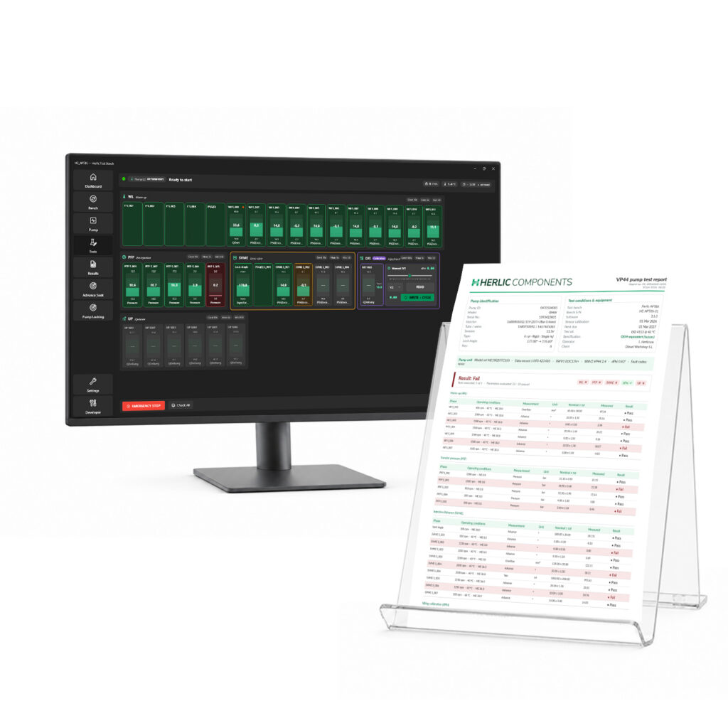
A multi-page A4 PDF, generated per run. It is the deliverable — the thing your customer keeps and the reason the pump can be stood behind.
What is on it
- Pump identity — Bosch part number, model, injector, tube and valve set, supply voltage, pump type (cylinder count, rotation direction, whether it has pre-injection), lock angle nominal and measured, and key.
- Test conditions and equipment — the bench and its serial number, the software version, the sensor calibration date and its next-due date, the test oil and its specification, the operator, and the client.
- What the control unit reported — model reference, data record, both software versions, the idle-timing calibration value and the stored fault codes, read directly off the pump’s own electronics.
- The verdict — pass or fail, with the count of tests executed, the count of measured points passed, and a per-test summary.
- The results — one table per test, one row per measured point: the phase, the conditions it was measured at, what was measured, its unit, the nominal and its tolerance, the measured value, and pass or fail. Failing rows are tinted, and any control-unit error bits recorded during a phase are flagged on their own row.
- Observations and a signature line for the operator.
And around it
- Every page carries the workshop’s logo and name, the report number, the date, the bench serial number, the test oil and the page number.
- Your name on it. Your company name and contact block appear on every page, set once and editable at the point of generating a report. Your logo is applied at installation.
- Every run is kept. One file per completed run, written the moment the run finishes, holding the full pump identity, everything read from the control unit, every phase, every measured point with its verdict, and every individual measurement sample. Nothing is pruned.
- Reports can be re-generated at any time, so a customer coming back a year later can be given the original certificate again.
- Nothing leaves the building. There is no API, no cloud and no workshop-management integration. Your test data stays on your PC.
The certificate does not just say the pump delivered correctly. It records what the pump’s own electronics said about themselves at the same moment.
What we supply, and how it connects
- The control electronics.
- The sensor set — two flowmeters, pressure sensors, temperature sensors and a shaft encoder.
- Ten relay outputs — oil pump, tank heater, tank cooler, inlet-line cooler, pump power, rotation direction, counter, pulse signal, beacon and a spare.
- A PC with the software installed and configured, plus both USB adapters: PCAN-USB to the bench electronics and an FTDI adapter to the pump’s diagnostic line.
- The pump database and the factory-derived test plans.
The drive motor is commanded through a 0–10 V analogue speed signal to your existing speed controller, and the shaft encoder we fit measures injection advance. That is the whole mechanical interface to your machine.
Compatibility is confirmed bench by bench, before we quote. The conversion generalises because our electronics talk to the motor drive and the sensors rather than to a particular make of bench — but the honest answer to “will it fit mine” is that we look at yours. Tell us the make and model and what is already fitted, and we will tell you.
Specifications
The conversion and its software, as they ship.
| System | |
|---|---|
| What it is | Retrofit control system for diesel injection-pump test benches — custom electronics, sensor set and Windows software |
| Pumps | Bosch VP30 and VP44 with PSG5 control units. 110 pump part numbers, 147 identifiers. |
| Control units | PSG2/PSG5 Opel; PSG5 with pre-injection; PSG5 with pre-injection, Ford, including immobilizer unlock. Three diagnostic protocol variants. Not PSG16. |
| Test plans | 109 original Bosch factory test plans |
| Interfaces | |
| To the bench | CAN bus to the control electronics. The drive motor is commanded by a 0–10 V analogue speed signal. |
| To the pump | CAN to the pump’s electronics, and K-Line / KWP2000 to its diagnostic port |
| To the PC | Two USB adapters, both supplied — PCAN-USB to the bench electronics, FTDI to the diagnostic line |
| Measurement and control | |
| Measured | Delivery and return quantity, injection advance angle, shaft position, two pressure channels, four temperature channels, bench speed, bench alarm states |
| Read from the pump | Reported speed, fuel temperature, solenoid energising time, injection-angle feedback, commanded quantity, status and self-test words, immobilizer state, fault codes, software versions, serial number, stored idle-timing value |
| Control | Closed-loop speed control against measured shaft speed. Relay control of oil pump, tank heating and cooling, inlet-line cooling, pump power, rotation direction and signalling. |
| Not measured | Solenoid drive current and supply voltage |
| Software and output | |
| Runs on | Windows 10 or 11, 64-bit. The PC is supplied with the software installed and configured. |
| Languages | Spanish and English, switchable in the application |
| Output | Multi-page A4 PDF test report, generated per run |
| Stored | Locally on the PC. Every completed run kept permanently with every individual measurement sample; reports re-generatable at any time. |
| Network | None. No API, no cloud, no workshop-management integration. |
| Fitting and commissioning | |
| Installation | By Herlic Components, or by a technician we have trained |
| Test oil | ISO 4113 |
Automate your pump testing.
Tell us your bench and we will confirm what the conversion involves, or book a demo and watch a run end to end.